In This Issue
Modular Synthesis for Beginners – Oscillators, Part 1: Analog Waves
If you’re going to be programming synthesizers, you’ll need to understand what oscillators do.
The sounds produced by synthesizers come from modules called oscillators. A lot can happen to the sound after it leaves the oscillator. In fact, the sound of a raw oscillator by itself isn’t very useful in most musical situations. But with only rare exceptions, if your patch doesn’t have an oscillator, you won’t hear anything.
Oscillators come in a variety of types, each generating its sounds in a different way. Some modules are hybrids that can produce sounds using several different methods. This month we’ll start our adventure in synthesizer sound design by taking a close look at the traditional analog oscillator.
A note for purists, before we go on: Everything that happens in a computer is digital, not analog. When I use the term analog here, I’m referring to digital oscillators that sound very much like the true analog oscillators that started the synthesizer revolution many years ago.
Last month, in the first installment of this column, I introduced the concepts you’ll need to know in order to use the VCV Rack software. If you missed that column or would like to review it, you’ll find it HERE.
This month’s tutorial patch uses an analog oscillator from VCV, which is installed when you install VCV Rack. You’ll also need the module sets from Bogaudio, ML Modules, and Nysthi in order to use the patch. CLICK TO DOWNLOAD
Even if you don’t have VCV Rack running at the moment, or if you haven’t installed it yet, you can watch and listen to the concepts in this month’s column in the video.
What’s in a Wave?
An oscillator is a device that produces a repeating signal—a signal that rises and falls over and over. The rising and falling is an oscillation; that’s where the term comes from. The shape of the signal as it rises and falls from moment to moment is called the waveshape or waveform.
The waveforms produced by analog oscillators have simple shapes, because those shapes were easy and economical to produce 50 years ago, when analog hardware synthesizers were first being built. Each waveform has its own characteristic sound. Explaining exactly why each of them sounds different would take us off on a bit of a tangent. At the moment, what you need to know is that analog oscillators typically produce four types of waves: sine waves, triangle waves, sawtooth waves, and square waves. Square waves are also called pulse waves, for reasons that will become apparent shortly.
The speed with which the wave rises and falls is its frequency. If the frequency is too low (less than 20 cycles per second), you won’t hear anything except for maybe some clicking noises. If the frequency is too high, again you won’t hear anything. The range of human hearing is generally stated as being from 20 cycles per second (20 Hertz, abbreviated Hz) at the low end to 20,000 cycles per second (20 kiloHertz, abbreviated kHz) at the high end. Older people generally lose the ability to hear the higher frequencies.
This Month’s Patch
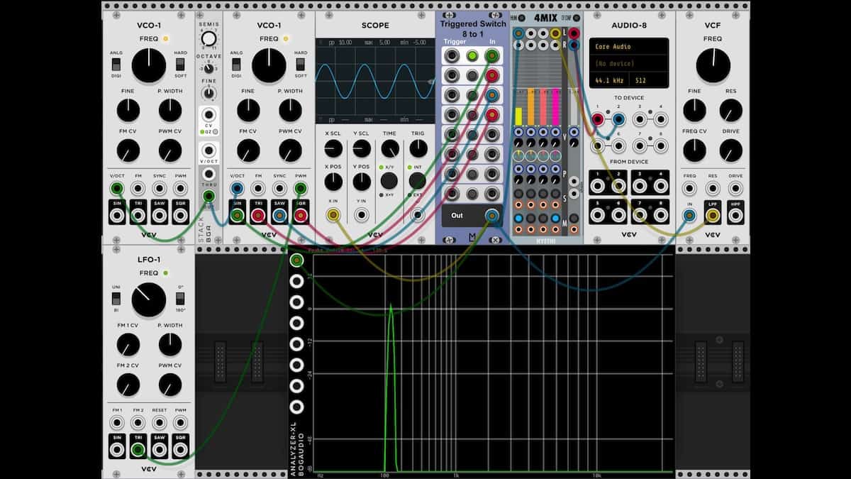
In this month’s tutorial patch, the four outputs of an analog oscillator are patched into the 8-into-1 switch from ML Modules. To choose which wave you’ll listen to, click one of the buttons in the center column of the switch module. (You could accomplish the same thing by moving a single output cable from one output jack to another, but using the switch is easier.)
The switch’s output switch goes into the Nysthi 4-channel mixer, and from there to the audio output module. It also goes into the VCV Scope module, so we can look at the waveform, and into the Bogaudio Spectrum Analyzer, so we can view its harmonic content.
The Bogaudio Stack module controls the frequency of the oscillator. This makes it easy to switch the pitch up or down by octaves, which can be convenient for listening and testing.
Waves Upon Waves
After assigning the Audio-8 output module to your interface hardware, click the top button in the Triggered Switch. Then click the button near the lower left corner of the 4Mix module to unmute that mixer channel. You should now be hearing the sine wave output of the VCO.
By the way, VCO is an acronym for voltage-controlled oscillator. If you right-click in an empty area of the VCV interface to open the browser and then type “vco” in the search field at the upper left corner of the browser, you’ll find all of the oscillators you’ve downloaded and installed.
The sine wave sounds very dull and muted. In the Scope you can see that the waveform rises and falls smoothly. The Analyzer shows a peak around 100Hz, and just about nothing else.
Click the second button in the Switch. Now you’re hearing VCO-1’s triangle wave. The shape in the Scope has “corners” at the top and bottom of the waveform, and the Analyzer shows a few weak overtones, which add a bit of buzz to the tone.
The third button unleashes the sawtooth wave. It has a much more buzzy sound, and the Scope shows the characteristic sawtooth shape: in each cycle the wave rises gradually and then falls suddenly.

The fourth button in the Switch introduces the square wave. For some reason, the square wave sounds subjectively louder, even though its peak-to-peak energy is the same as that of the sawtooth.
While listening to the square wave, turn the P. Width (pulse width) knob on VCO-1 and watch the scope. You’ll see the waveform’s pulse get wider or narrower, and the sound will get thinner. In a classic VCO, this knob affects only the square/pulse wave, but in some hybrid oscillators a knob with the same name will also affect other waveforms.
Next, go back to the sine wave (the top button in the switch) and click the switch in the VCO that’s labeled ANLG/DIGI (in other words, analog or digital). When this switch is in the analog position, the waveform will be less “perfect.” The sine wave will acquire some weak overtones. Try using this switch with the other waveforms as well, and look at the waveform in the scope. The computer code in VCO-1 attempts to add the same imperfections that you’d hear in real analog hardware.
Waveform Modulation
A static waveform gets boring very quickly. The ear prefers to hear sounds that have some movement, some animation. One of the important techniques for doing this is to modulate the waveform. Most oscillators, except for the very simplest, have inputs with which you can change the waveform while the music plays.
If you’ve been following along, you’ve already heard this effect when you turned the pulse width knob in VCO-1. But with only one mouse and a whole bunch of knobs, you want a modular synth to be able to mutate the waveform for you automatically.
To do this, I’ve added an LFO-1 module to the tutorial patch. An LFO is a low-frequency oscillator. Its output will usually be below 20Hz, so you don’t want to listen to it directly, but you want to use it to modulate something else.
After selecting button 4 in the Switch so that you’re hearing the VCO-1 square wave, turn up the PWM CV (pulse width modulation control voltage) knob in VCO-1. This knob controls the amount of LFO signal that will reach the square/pulse wave. You should hear a nice rolling sound. Try turning the LFO’s Freq (frequency) knob up and down to hear what happens to the modulation.
FM (No Static at All)
Frequency modulation (FM) is a standard way of creating more complex and interesting waveforms. In this month’s patch I’ve attached the sine wave output of a second oscillator to the FM input of the oscillator you’re listening to.
Go back to the sine wave output of the main VCO (switch button 1) and then turn up the FM CV knob in the VCO. You’ll hear a complex waveform with a variety of overtones, and the basic pitch will change. In an analog oscillator, tuning the pitch of an FM tone so that it works with the other instruments can be rather tricky, but the sound is definitely interesting.
Sync or Swim
Another standard technique with analog oscillators is to synchronize one oscillator to another. That’s what the Sync input jack on the VCO-1 is used for. Typically, the synced oscillator is tuned an octave or more higher than the oscillator that’s the source of the sync signal. The source of the sync signal is usually called the master. Instead of listening to the master oscillator directly, usually you only listen to the synced oscillator.
Each time the signal at the sync jack rises past zero, the synced oscillator is compelled to “start over,” resetting its waveform. As a result, its tone color is a composite of the fundamental pitch (which is dictated by the master oscillator) and its own pitch.
The hard/soft switch in VCO-1 gives us a choice of two types of sync. They have quite different tones, and both are useful. Try sweeping the pitch of the synced VCO and listen to what happens.
Other Ideas
Quite often, a filter module will be used to shape the sound of an oscillator. When you get tired of listening to the plain analog waveforms in this month’s patch, try patching a filter between the oscillator output and the mixer input. I’ve included a filter in this month’s patch; it’s connected to input 4 of the mixer. As I’ll explain in more detail in a future column on filters, a filter basically removesovertones from the oscillator’s sound. That’s why using a sawtooth or square wave as the filter’s input is recommended. If you route a sine wave to a filter, not much will happen, because the sine wave has no overtones for the filter to remove.
In this column you’ve learned about analog-type waveforms and how to use waveform modulation and sync. In the next couple of columns we’ll look at some other types of oscillators, including wavetable, FM, and physical modeling.


Arturia Rev OCEAN – a Big, Evolving Reverb Ambience Processor

Cherry Audio Releases an Ensoniq ESQ-1 Synth in Software (updated with 2026 features)
Gforce Software Releases Official Prophet 5 Plug-in with Sequential

Arturia’s New MiniLab 37 MIDI Controller

Novation’s Launchkey 61 MK4 White Keyboard Controller With Five Octaves
Arturia’s New MiniLab 37 MIDI Controller

When In Rome…

Introducing Absurdly Quiet Piano Pro

New From AAS – Organix for Chromaphone


