
A Lesson From Christmas Past…Jim Aikin’s Modular Synthesis: Modulation

Modulation changes everything when you route control signals from sources to destinations.
Original lesson from December 2019
Turning knobs by hand while a synthesizer is producing a tone is a great way to add expression to your music. Most of us have only two hands, however, and quite often one or both of them will be busy playing notes on the keyboard. More often than not, you’ll find yourself using preconfigured modulation signals to make changes in the sound while the notes play. Using as many as a dozen modulation signals at once, all of them doing different things to the sound, is not unusual.
Several different kinds of devices, such as envelope generators, LFOs (low-frequency oscillators), and step sequencers, can create modulation signals. In a future column I’ll have a lot more to say about various modulation sources. This month we’ll start the discussion by taking a closer look at the signals themselves.
Quite often, modulation signals are referred to as CVs. This abbreviation stands for control voltage. In a digital synth, the signals are not actually voltages; they’re numerical (digital) values, but the term CV is still used and means the same thing. In a real analog synth, the control signal exerts an electrical pressure on whatever is receiving the signal. The amount of pressure is measured in volts. In a hardware modular synthesizer such as a Eurorack system, the typical range of voltages is between -10 and +10 volts.
In a digital synth, the voltage in a CV signal is actually just a number, because everything in a digital synth is numbers.
When you’re making music, though, that often doesn’t matter. Different instruments may represent the numerical values in a CV in different ways—for example as -100% to 100%, or as -128 to +127. In the software modular VCV Rack system [Modulation.vcv], which we’re using in the examples in this column, CV signals are represented in the range -10 to +10, exactly as if they were voltage levels.
Receiving CVs
In order for a CV signal to do anything, it has to be routed from a source to a destination. For instance, if you want to control a filter’s cutoff frequency using a CV from an LFO, you have to route the output signal coming from the LFO to the filter’s cutoff frequency input. Various instruments allow you to do this in various ways. Some instruments use onscreen patch cords (or in the case of hardware modular synths, physical patch cords) to link the CV source to an input jack on a destination module. Some instruments use drop-down menus in the destination module, with which you can select a specific CV source from a list. Some instruments have matrix modulation panels, in which sources can be paired with destinations.
In order for the CV to have an effect on a given sound parameter, that parameter has to have a CV input. If there’s no suitable CV input, the parameter can’t be controlled using a CV (though you might still be able to control it using a knob). In a simple filter module, for instance, you might find a CV input for the cutoff frequency, but no input for the amount of resonance. These days, the trend in instrument design is to give musicians more types of CV control over the sound.
Attenuation & Mixing
Your instrument will probably provide a method with which you can adjust the amount of effect the CV signal will have on the sound. The general term for this adjustment is attenuation. When a signal is attenuated, less of it passes through the attenuator. If the attenuator is set to zero, no signal will pass through, and your CV will do nothing.
You’ll find various types of CV attenuation on various synths. In a modulation matrix, it’s usual to have the level of the attenuator displayed as a number. In a modular instrument, you may find a knob for attenuating the signal at the CV input. In some modular instruments, you may need to use a separate module as the attenuator. CV source modules with an output level control are also common.
It’s often useful musically to send two, or in rare cases three, CV signals to a single parameter of a module. If the module provides only one CV input per parameter, you’ll need to use a separate mixer module of some sort to add the CV signals together and then send the mixer’s output to the destination.
Another very common musical task is to control the amount of one CV signal using another CV. A simple example of this is controlling the amount of an LFO sine wave being sent to an oscillator’s pitch input to produce vibrato. On most synths, the amount of CV coming from the LFO can be controlled using the mod wheel. In essence, when you do this you’re multiplying one CV value by another CV, rather than adding them. In a modular synth, you may need to use a separate VCA (voltage-controlled amplifier) module to multiply one CV by another.
Polarity & Range
The terms unipolar and bipolar are used in many CV-based modulation systems (see Figure 1). A unipolar signal goes from 0 to whatever maximum the system is set up to allow—for example, from 0 to 100. A bipolar signal has a range that dips below zero as well as rising above zero—for example, from -100 to +100. When the signal is below 0, it’s upside down; that is, it’s inverted.

In a modular synth, you may find that some modules expect to receive input CVs that are unipolar, while others can respond to bipolar signals. Some modules may work best with a CV range from 0 to +5 volts (unipolar) or -5 to +5 volts (bipolar), while others can respond to signals from 0 to 10 volts or from -10 to +10 volts.
Envelope generators, for example, typically output a unipolar signal. The envelope CV travels from zero (when the envelope generator isn’t doing anything) to some positive value, and eventually falls back to zero. You may be able to invert a positive-going unipolar CV so that it travels from 0 down to -100% instead of from 0 up to 100%. Some envelope generators have a separate jack with an inverted output or a switch for inverting the output. In a modular system, you may need to use a separate inverter module to do this.
A module that can either attenuate or invert a CV signal (or both at once) is often called an attenuverter. It’s an ugly word, but descriptive.
Shapes
A CV signal can have any shape at all. It can be a sine wave, or stepped, or a contour with a fixed shape, or random. In some cases you may want to control the shape of a CV using a different CV. For instance, an envelope generator might have an input for the rate of the attack segment of the envelope. If you send a CV from an LFO to this input, some of your envelope attacks will be faster, and some will be slower.
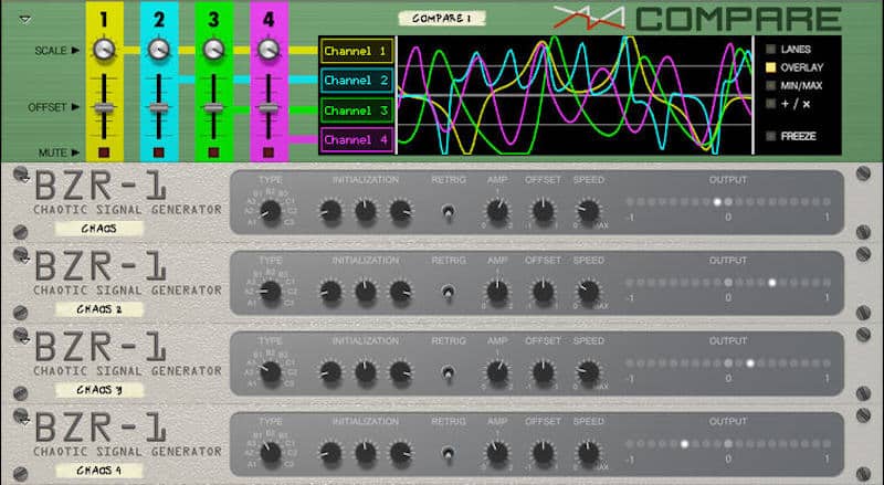
Once in a while, figuring out what a CV is doing (or not doing) can be a challenge. Some software-based modular synths have display modules that can show you on screen what the CV is doing (see Figure 2).
Destinations
What can you do with CV modulation? Anything your synth allows you to do. You’ll probably find dozens of possibilities. (If all else fails, try reading the manual.) In addition to modulating the filter cutoff and resonance, which I mentioned above, an oscillator’s pitch (also mentioned), or an envelope generator segment’s rate (ditto), you may be able to modulate the oscillator’s waveform, the loudness or panning of the output signal, the amount of an effect such as reverb, the rate of an LFO, the number of active steps in a step sequencer, the signal routing in a switching matrix, the type of chord produced by a polyphonic chord generator, and so on. Exploring these possibilities is one of the best ways of making your electronic music more colorful, expressive, and stylistic.


